Concrete Hose Repair and Pipeline Accessories: Weld-On Ends, Ferrules and Snap Couplings
Our engineering board explains how worn placing hose and delivery pipe are restored to service: when repair makes sense, how end fittings are fitted and tested, and which accessories decide the safety of the joint.
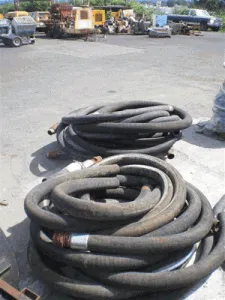
Concrete hoses with end fittings.
Repair or Replace: When Restoring a Concrete Hose Is Justified
Placing hose and delivery pipe wear out unevenly. The rubber body of a hose often outlasts its end fittings, and a worn coupling groove or a loose ferrule is far cheaper to correct than a full hose. Repair is justified when the hose body is sound and only the end fitting, the clamp or the nozzle has failed. It is not justified when the body itself has reached the end of its life, because a new fitting on a weak hose just moves the failure to the next weakest point.
Conditions That Allow Repair
- Worn or damaged end fitting: groove worn through, flange thinned, thread damaged or ferrule loose, with the hose body intact beside it.
- Sound hose body: cover without deep cuts, no bulges or soft spots, uniform stiffness along the length, and a uniform inner tube when checked at the cut end.
- Enough length left: cutting back behind a failed end removes length, so the finished hose must still meet the length the job needs.
Conditions That Call for Replacement
- Exposed or corroded reinforcement, wire kinks or broken cord.
- Bulges, blisters or layer separation between the tube and the carcass.
- A thin or uneven inner tube, or flat spots caused by kinking.
- A history of over-pressure or an unknown service history.
Whoever performs the repair, the standard is the same: the fitting must be installed to the hose manufacturer's or fitting manufacturer's procedure and tested before it returns to the pump. A repair that is not tested is only a guess.
Weld-On Ends: Carbon-Steel Fittings for Pipe and Heavy-Duty Hose Assemblies
A weld-on end (also called a weld groove end or weld-on coupling end) is the machined steel ring that carries the coupling groove for the snap clamp. It is welded to rigid delivery pipe or to the steel stem of a hose end, so that the joint can be clamped to the next section. Fitting a heavy-duty end in place of a standard end raises the wear life of the groove, which is the part of the joint that the clamp loads on every pour.
Types and Sizes
Weld-on ends are made in standard, heavy-duty, metric, grooved and male and female patterns, and in sizes that typically run from 1-1/2" up to 5" for placing lines. They are machined from carbon steel on CNC equipment, so that the groove depth, the flange face and the seat for the gasket are held to the dimensions that the clamp expects. The pattern must match the clamp and the gasket in use, because a groove of the wrong depth or width can let a clamp close without seating on the bearing face.
Installation Procedure
- Prepare the pipe or stem: cut square, remove the old end and inspect the wall thickness. Measure it with an ultrasonic gauge, and do not weld on a wall that is worn below the minimum.
- Machine the weld joint: bevel the pipe and the end to the joint design in the welding procedure, and clean to bare metal back from the joint. Remove paint, scale, oil and concrete residue.
- Fit up: seat the end square to the pipe axis, and align the groove face to the pipe center line. Tack weld at several points, and check the alignment again, because distortion cannot be removed after the weld is complete.
- Weld to a qualified procedure: carbon steel is welded to a written welding procedure specification (WPS) by a qualified welder, using a filler metal matched to the base metal (low-hydrogen electrodes or a solid wire for gas-shielded welding are common). Preheat and interpass temperature depend on the carbon equivalent and the wall thickness, and are set by the procedure. Make the root pass, then the fill and cap passes with full fusion at the toe of the weld.
- Control cooling: let the joint cool slowly and keep it dry. Do not quench it, because rapid cooling of carbon steel can harden the heat-affected zone and crack it.
- Build up the groove: on heavy-duty ends the groove can be built up with wear-resistant weld metal so that it takes longer to wear through under clamp loading. Machine or grind it back to the groove dimensions afterwards.
- Inspect and test: check the weld visually, then by dye penetrant or magnetic particle examination for surface cracks. Gauge the groove and flange dimensions against the clamp and the gasket, and pressure test the assembly (see the testing section).
Do not weld on cast iron or on pipe that is hardened for wear without the pipe manufacturer's procedure. Hardened or heat-treated pipe loses its wear layer near the weld and can crack, so the manufacturer must approve the method.
Ferrule Installation by Internal Expansion
A ferrule is the metal end of a hose. It consists of a stem (the inner tube that goes into the hose bore) and a shell (the outer sleeve that surrounds the hose). The hose body is held between the two. When a hose end is damaged, the practice is to cut the hose back behind the original ferrule and fit a new stem and shell, expanding the stem into the hose from the inside so that the hose is gripped on both sides.
Why Internal Expansion Holds
The stem is expanded radially against the bore of the hose, and the rubber and the reinforcement are pressed against the shell. The result is a mechanical lock on the carcass, not just a friction fit on the cover. The hose cannot back out under internal pressure, because the inner and outer surfaces both grip the reinforcement. The grip comes from the radial interference, so the expansion dimension is a controlled value, and it is checked after every installation.
Installation Procedure
- Measure and cut: mark the cut behind the original ferrule so that the sound hose body is reached. Cut square with a saw or a hose cutter, and keep the reinforcement from fraying.
- Remove the old ferrule: pull the stem and strip the shell from the hose. Clean the bore and the cover, and inspect the cut face for cracked rubber, corrosion of the wire or separation of the layers. If any are found, cut back again or retire the hose.
- Select the fitting: match the stem and shell to the hose ID, to the wall thickness and to the pressure class. The end can be a heavy-duty groove end, a threaded end or an adapter, and the size range for placing hose usually runs from 1-1/2" to 5" and larger.
- Fit the shell and the stem: slide the shell over the hose, lubricate the bore as the fitting manufacturer allows, and push the stem in to the stop. Keep the stem straight and fully seated.
- Expand the stem: use the expansion tool (a mandrel, a segmented expander or a hydraulic expander) to the diameter given in the fitting data. Expand in a single controlled operation, and do not over-expand, because it cuts into the carcass and thins the tube.
- Crimp or swage the shell where the design requires it: some assemblies are also compressed radially to a specified diameter. Measure the finished dimension with a go and no-go gauge.
- Verify: check the overall length, the alignment of the end face and the flange squareness. Mark the hose with the fitting date and the repair record number.
- Proof test: pressure test the assembly before it goes back to the pump.
Heavy-Duty Snap Couplings with Safety Pins
The snap coupling (clamp coupling) joins two grooved ends with a hinged or two-part clamp and a gasket. It is the part of the line that the crew opens and closes on every pour, so its condition decides how safe the line is.
Construction and Selection
- Material: forged or fabricated steel clamps are preferred over cast designs for strength and for resistance to cracking under shock loading. Check the manufacturer's rating for the body, the bolt and the handle.
- Profile: clamps come in grooved, heavy-duty and metric patterns, and in fixed or adjustable versions. The clamp must match the groove of the end fitting and the gasket, because a mismatch leaves the joint seated on too small an area.
- Gasket: use the gasket that fits the groove and the working pressure. It must be fully seated, with no folds or nicks.
- Safety pin: the locking pin keeps the clamp closed if the handle is hit or the line vibrates. A clamp without its pin is not in a safe condition.
- Handle and surface: a comfortable, strong handle reduces the temptation to hammer the clamp closed. Zinc plating or paint protects against corrosion, but is not a substitute for inspection.
Closing and Checking a Snap Coupling
- Clean both grooves and the gasket seat. Remove concrete residue, because it stops the gasket seating.
- Fit the gasket in the groove, then bring the two ends together square to each other.
- Close the clamp over both grooves and make sure it bears on the full circumference.
- Latch the handle and install the safety pin every time.
- Check that the clamp cannot be moved by hand and that there is no gap at the faces.
When to Retire a Clamp
- Cracks, bent bodies, stretched or worn bolts, and handles that do not close fully.
- Worn bearing faces that let the clamp sit unevenly on the groove.
- Missing, bent or replaced pins that do not lock.
- Any clamp that has been struck, dropped under load or heated.
Shotcrete Nozzles and Wear Tips
Shotcrete and gunite nozzles take the most abrasive duty in the line, because the mix is accelerated at the tip. Nozzle bodies and tips wear from the inside out, and wear shows up as a widening of the bore and a change in the spray pattern. Replacement nozzles and tips are normally supplied in the 1-1/2" to 2-1/2" range for tunnel, pool and repair work. Check the bore with a gauge at set intervals, and replace the tip when it exceeds the manufacturer's wear limit, not when it starts to spray badly. See the guide to shotcrete hose selection for more detail.
Technical Summary: Repair Operations and Verification
| Operation | Applies To | Key Control | Verification |
|---|---|---|---|
| Weld-on end installation | Rigid pipe and hose stems | Qualified WPS, preheat, controlled cooling, square fit-up | Visual and surface NDT, groove gauge, pressure test |
| Ferrule by internal expansion | Hose ends | Sound cut face, correct stem and shell, controlled expansion dimension | Go and no-go gauge, length and squareness check, proof test |
| Snap coupling and gasket replacement | All grooved joints | Matching profile and pressure class, gasket seated, pin fitted | Visual check, no gap, no movement, leak check under pressure |
| Nozzle and tip replacement | Shotcrete and gunite lines | Bore size to wear limit, matching thread or coupling | Bore gauge, spray pattern check |
Proof Testing and Records After Repair
A repaired assembly goes back to the pump only after it has been pressure tested. The usual method is a hydrostatic test with water, to a multiple of the working pressure set by the hose or fitting manufacturer (a factor of 1.5 is commonly used). The test pressure and the hold time come from the manufacturer's procedure, not from this guide.
- Restrain the assembly: secure it with straps or in a test cage, because a failing joint releases energy suddenly.
- Bleed the air: trapped air is compressible and makes a failure more violent.
- Keep personnel clear: no one stands near the assembly or its couplings during the test.
- Check for leaks and movement: look for weeping at the fitting, slip of the hose in the ferrule or deformation of the end.
- Record: log the serial number, the repair date, the fitting type, the test pressure and the result, and mark the hose.
Cleanout: Cleaning Balls and Water Flushing Extend Fitting Life
Couplings and accessories for concrete lines.
Concrete left in a line hardens on the bore and in the grooves of the fittings. It wears the inner tube, packs the clamp seats and speeds up wear on repaired ends. Use a cleaning ball after every job and push it through the line with water, so that the concrete is removed from the whole length. Direct the discharge into a washout pit or a ball catcher, because the ball can leave at high speed. Compressed air stores far more energy in the line than water, so use it only as the pump manufacturer allows, with a rated cleanout cap and a restrained end. Never use air on a damaged hose.
Safety Practices for Repaired Lines
- Fit whip checks or safety cables across couplings on elevated and high-pressure joints, and especially on boom end hoses.
- Keep everyone out of the line of discharge and clear of couplings when the pump starts. Reverse the pump to relieve pressure before opening any coupling.
- Do not put a repaired assembly into service on a pump rated above the pressure it has been tested for.
- Follow the pump manual, ACPA safety guidance and the OSHA concrete construction rules in 29 CFR 1926 Subpart Q.
Recommended Reading and Sourcing
Compare new hose sizes and pressure classes in our concrete pumping hoses guide. When a hose body is too worn to repair, a used replacement can be a lower-cost alternative if it is inspected against the criteria above.
Recommended Component & Pipeline Accessories Guides
Expand your technical layout planning by accessing our specialized hardware libraries: